The Kea'au Middle School Participation in:
The Great Hawai'i Earthquake Simulation Experiment
a GPS Project
In Partnership with UHM
KMS and the GPS Radome on a Stick
![]()
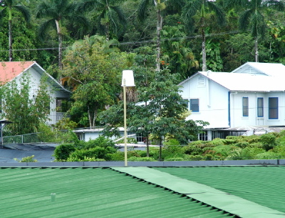
GPS Radome above the "A" building
![]()
Zoom
![]()
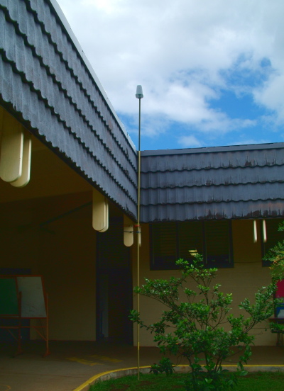
View in the courtyard of setup - Pole is Bungy corded to wood - held firmly to the corner.
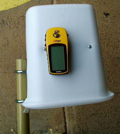
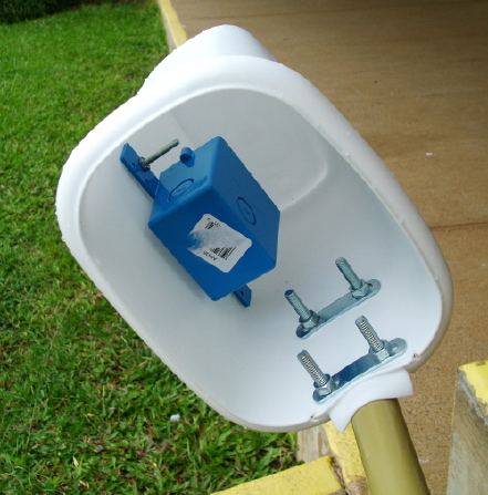
Construction: Two 10 foot tall "antenna mast" pieces were joined together to make a "20 foot tall" mast. A small plastic trash can was connected with u-bolts. Inside a plastic bracket was attached to the side of the trash can. Velcro was placed on the back of the GPS and the inside of the bracket for fixing the GPS to the mount.The Pole is wedged into the corner and held there with bungy cords. The radome is oriented parallel to the left side to maintain a standard GPS unit position. Pole vibration is minimal. I'm estimating that day to day positioning should be within 1-2 cm.
Variations may arise from
student interaction with the pole :-(
Not twisting the pole to the same angle
Not placing the base in the same position
Rationale for this setup: we did not have any easily / safely accessible flat roof surfaces with acceptable security (positional and theft)
Setting up for the Earthquake will be a bit challenging!!! fortunately, the roof is only about 20-30 degrees out of alignment with the earthquake direction. So, some rope, bungy cords, inspiration and cooperation will hopefully do the trick!!!
Basic Data
UTC Data Date Mean Latitude (N) Mean Longitude (West of Greenwich) Mean Elevation (Meters) Running Mean of Means>>>
What an odd statistic - I'll put all the data together some day19.62169801 -155.0371055 124.6626062 Cumulative Mean>>>
from........ points2006 - 05 - 03 19.62168959 -155.0371088 125.8706662 2006 - 05 - 04 19.62169451
-155.0371011 125.726713 2006 - 05 - 05 19.6217043 -155.0370995 125.8111217 2006 - 05 - 06 19.62170281 -155.0371097 121.7532782 2006 - 05 - 09 19.62168541 -155.0371032 124.3899418 2006 - 05 - 10 (1 sec data) 19.62171142 -155.0371109 124.3879158 The overflow of the 10,000 data points turned off the recording, so I lost a day.
Hmmmmm...
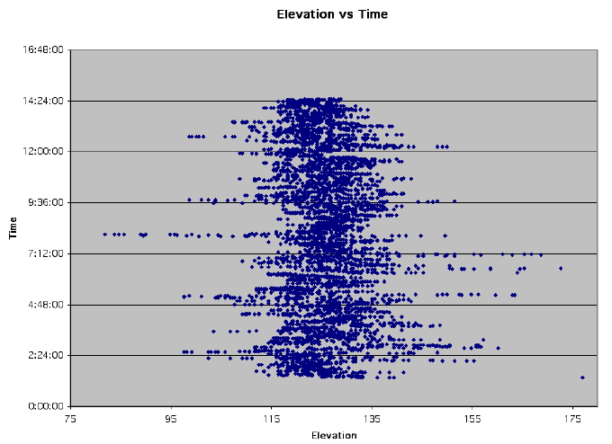
Looking at the data for the second day - I found the elevation data to be the most interesting...
We went from 81.85 meters to 177.02 meters!
The clustering of the elevation excursions in particular time segments suggests that these might be associated with Satellite Rise and Set times. These times carry with it a higher chance of ground and building reflections - and this might give the anomalous results.
When I removed data points with elevations Higher than 136 and less that 115 (roughly 2 sigma) the mean latitude and longitude changed only slightly, but the latitude "tightened up" a bit. Some of the extremes of East and West were eliminated.
Looking at more data - there appear to be two sorts of data oscillations - the Big ones (3 sigma +) and smaller ones about + and - 1 sigma. I'm going to guess - the big variations are Satellite Rise and Sets, and the small ones are ionospheric scintillation effects. An alternate, suggested by recent Israeli work using cell sites to examine weather / they represent scattering or attenuation of satellite signals due to the rain. What would be nice - data on satellite elevation and satellite signal strength at the same time as the position data - then we add in local weather :-) Any one with ideas on this - let me know!!!
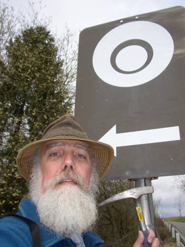
![]() At the Otting Suevite Quarry - Ries Impact Crater - Germany |
|
Interesting info I dug up on the net :-)
Note: "cheap" = consumer GPS units are single frequency "L1"
devices -
Dual frequency L1/L2 devices can attain cm accuracy with integration,
but are 20 to 50 times more expensive!!!
With SA off, the inaccuracies and wild movements we see in position seem to come from ionospheric propogation delay and scintillation - I suspect some come from times when satellites are low to the horizon (traversing more of the ionosphere) and also potentially prone to reflections off buildings.
Modern navigational systems that use radio-wave signals reflecting from or propagating through the ionosphere as a means of determining range, or distance, are vulnerable to a variety of effects that can degrade performance. In particular, systems such as the Global Positioning System (GPS), that use constellations of earth-orbiting satellites, are affected by space weather phenomena. In principle, the GPS uses known positions of satellites and their distances from a receiver to determine the location of the receiver.When charged particles ejected from the Sun arrive at the Earth, they can cause perturbations in the geomagnetic field. Another effect is that in the ionosphere the electron density (number of electrons in a given volume) can vary considerably, both in time and space.
A GPS receiver uses radio signals from several orbiting satellites to determine the range, or distance, from each satellite, and determines from these ranges the actual position of the receiver. The radio signals must pass through the ionosphere and in so doing they are subjected to variations in the electron density structure of the ionosphere. Changes in the electron density due to space weather activity can change the speed at which the radio waves travel, introducing a "propagation delay" in the GPS signal. The propagation delay can vary from minute to minute, and such intervals of rapid change can last for several hours, especially in the polar and auroral regions. Changing propagation delays cause errors in the determination of the range, or "range errors".
The performance of single-frequency GPS receivers using Code Phase Tracking techniques can be significantly degraded by the ionospheric propagation delays. Use of dual-frequency GPS receivers can, under some conditions, compensate for most of the ionospheric propagation delays by measuring the different delays at the two frequencies. Ionospheric delay corrections for a region can be determined from a network of precisely-positioned dual-frequency receivers and then be transmitted in near-real-time to users of single frequency GPS receivers in the region. Such a system is operated by the Canadian Active Control System of Natural Resources Canada.
Another GPS technique uses Carrier Phase Tracking. In this technique, the phases of individual cycles of the carrier waves are compared. However, if the electron density along a signal path from a satellite to a receiver changes very rapidly, as a result of space weather disturbances, the resulting rapid change in the phase of the radio wave may cause difficulties for the GPS receiver, in the form of "loss of lock". Temporary loss of lock results in "cycle slip", a discontinuity in the phase of the signal. Very rapid variations (less than about 15 seconds) in the signal's strength and phase are known as "ionospheric scintillations" . Scintillations can be particularly troublesome for receivers that are making carrier-phase measurements and may result in inaccurate or no position information. Code-only receivers are less susceptible to these effects.
From another viewpoint, the GPS system provides continuous routine measurements of the Total Electron Content (the aggregate of electrons along each radio wave propagation path from satellite to receiver) along the multitude of varying signal paths to each receiving station in a regional or global network. These measurements permit the mapping of variations in the ionospheric electron density over a region. Such information can be of use for studying space weather phenomena themselves.
(colors are my accents)

From:
http://www.agu.org/revgeophys/yunck00/node7.html
Ionospheric Effects
Klobuchar [1991] and Yunck [1993] review the ionospheric effects on GPS positioning and techniques of calibration. While dual frequency correction has been practiced for decades, a few new twists have emerged. Wu and Melbourne [1993] describe a method of combining dual frequency phase and pseudorange to achieve slight noise reduction and a factor of two decrease in data volume when both data types are used. Of chief research interest today are the higher order effects that remain in the dual frequency observables. These can be traced to the interaction between the ionosphere and the earth's magnetic field, and to the differential bending of the L1 and L2 signals by the ionosphere. Brunner and Gu [1991] and Bassiri and Hajj [1993] note that higher order effects can exceed 1 cm under some conditions, with typical values of 1--3 mm. They offer modified dual frequency calibration techniques which may remove as much as 90% of the higher order error. An old technique of single-frequency ionosphere calibration, achieved by combining L1 phase and pseudorange data, was revived by Gold et al [1994] for orbit determination of the Extreme Ultraviolet Explorer. The technique sharply reduced postfit residuals and improved orbit consistency, yielding altitude accuracies of 30--40 cm for a satellite carrying a single-frequency receiver at an altitude of 500 km.The data bonanza from the GPS global network is stimulating new advances in ionospheric mapping. Until recently, GPS ion mapping has relied on local observations of total electron content (TEC) from individual receivers as they sweep out a band of the ionosphere each day. Mannucci et al [1993] introduced a globally simultaneous technique that features a gridded TEC model with stochastic local TEC adjustment and can produce images of the evolving global ionosphere with arbitrary time resolution. Such techniques can provide precise ionospheric corrections in near real time for single-frequency GPS users. Space based measurements will improve the fidelity and resolution of ionospheric images. Hajj et al [1994] examined through simulation and singular value decomposition the feasibility of 2-D and 3-D tomographic imaging by combining ground and flight GPS data. They found that measurements from space are better suited to both horizontal and vertical ionospheric imaging.
Ionospheric mapping depends on absolute one-way measurements rather than differenced data, imposing a requirement to calibrate the relative L1/L2 instrumental delay biases that would appear as biases in estimated TEC. This is typically accomplished by first calibrating each L1/L2 receiver bias, then solving for the individual satellite biases while estimating TEC [ Coco et al, 1991; Gaposchkin and Coster, 1993]. The global estimation technique permits the solution for individual receiver biases as well. Wilson and Mannucci [1993] report bias estimates with a day-to-day consistency of 0.2--0.4 ns, or about 3 times the precision of previously demonstrated techniques.